|
Dla tego produktu nie napisano jeszcze recenzji!
 ;
...instruction is ok.
...instrukcja jest ok.
Thanks/Dzięki
;
Documentation made available quickly and It is good quality. Thanks.
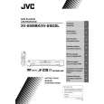
XV-S500BK/XV-S502SL
Check points for each error
(1) Spindle start error 1.Defective spindle motor *Are there several ohms resistance between each pin of CN201 "5-6","6-7","5-7"? (The power supply is turned off and measured.) *Is the sign wave of about 100mVp-p in the voltage had from each terminal? [ CN201"9"(H1-),"10"(H1+),"11"(H2-),"12"(H2+),"13"(H3-),"14"(H3+) ] 2.Defective spindle motor driver (IC251) *Has motor drive voltage of a sine wave or a rectangular wave gone out to each terminal(SM1~3) of CN201"5,6,7" and IC251"2,4,7"? *Is FG pulse output from the terminal of IC251"24"(FG) according to the rotation of the motor? *Is it "L(about 0.9V)" while terminal of IC251"15"(VH) is rotating the motor? 3.Has the control signal come from servo IC or the microcomputer? *Is it "L" while the terminal of IC251"18"(SBRK) is operating? Is it "H" while the terminal of IC251"23"(/SPMUTE) is operating? *Is the control signal input to the terminal of IC251"22"(EC)? (changes from VHALF voltage while the motor is working.) *Is the VHALF voltage input to the terminal of IC251"21"(ECR)? 4.Is the FG signal input to the servo IC? *Is FG pulse input to the terminal of IC301"69"(FG) according to the rotation of the motor?
(2) Disc Detection, Distinction error (no disc, no RFENV) * Laser is defective. * Front End Processor is defective (IC101). * APC circuit is defective. --- Q101,Q102. * Pattern is defective. --- Lines for CN101 - All patterns which relate to pick-up and patterns between IC101 * IC101 --- For signal from IC101 to IC301, is signal output from IC101 "20" (ASOUT) and IC101 "41"(RFENV) and IC101 "22" (FEOUT)?
1-22
|