|
|
|
Kto jest w sklepie?
Sklep przegląda 6043 gości |
|
Kategorie
|
|
Informacje
|
|
Polecamy
|
|
|
 |
|
|
Dla tego produktu nie napisano jeszcze recenzji!
 ;
jedyne do czego mogę mieć zastrzeżenie to jakość zdjęć zawartych w przesłanej instrukcji serwisowej ponieważ są fatalnej jakości, praktycznie nieczytelne. tak poza tym jestem zadowolony to jest to czego szukałem.
 ;
Wszystko w porządku.
Instrukcja czytelna i kompletna.
Dziękuję.
all right!
thank you.
;
Bardzo dobra instrukcja. Zawiera wszystko co potrzeba, polecam!
;
Instrukcja jest OK. Schematy czytelne, opisane niektóre procedury.
;
Instrukcja bardzo czytelna. zawiera co potrzeba. Polecam
UX-M5R
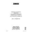
Removing the power board (See Figs. 16 and 17.)
Remove the left and right side panels. 1. Disconnect the wires from the connector CN901 on the power board. 2. Remove the tie bands bundling the wires. 3. Remove the screw M retaining the lug wire. 4. Remove the two screws N retaining the chassis . 5. Remove the power board by pinching the two studs retaining the power board using radio pliers, etc.
Chassis Lug wire Main board
Power transformer
Stud
CN901 Stud Tie bands
N
Fig.16
M
Power board
Radio pliers, etc.
Power board Stud
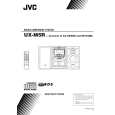
Removing the main board (See Figs. 18 and 19.)
Fig.17 Remove the left and right side panels. Remove the top cover. Remove the front panel assembly. Remove the CD mechanism assembly. 1. From the inside of the rear panel, remove the five screws P retaining the bracket. 2. Remove the two screws Q retaining the speaker terminal of the main board. 3. Remove the solder from the soldered part e that attaches the FM antenna wire to the antenna board. 4. Remove the three screws R retaining the rear panel, then remove the rear panel. 5. From the top side of the main body, remove the screw S retaining the bracket of the main board. 6. Remove the screw T retaining the regulator IC(IC302). 7. Remove the tie bands bundling the wires. 8. Disconnect the wire from the connector CN901 on the power board. 9. Remove the stud on the main board, and then take out the main board from the chassis.
Soldered part e Heat sink
Chassis
P
P
R Q
Fig.18
R
Regulator IC Main board FM antenna wire (IC302) Antenna board T Stud
CN901
S
Power board Bracket Power transformer Tie bands
Chassis
Fig.19
1-10
|
|
|
> |
|