|
|
|
Kto jest w sklepie?
Sklep przegląda 5961 gości |
|
Kategorie
|
|
Informacje
|
|
Polecamy
|
|
|
 |
|
|
Dla tego produktu nie napisano jeszcze recenzji!
 ;
Bardzo dobra jakość skanu, przystępna cena. Instrukcja serwisowa okazała się przydatna przy "reanimowaniu" dwudziestoparoletniego decka, który teraz pięknie gra :)
;
...instruction is ok.
...instrukcja jest ok.
Thanks/Dzięki
;
Documentation made available quickly and It is good quality. Thanks.
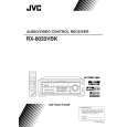
RX-8020VBK
Removing the power transformer (See Fig.17)
Prior to performing the following procedures, remove the top cover. 1. Disconnect the harness from the connector CN55 /CN56 and CN811 on the power trans1 board.
CN55/CN56 Power supply board
Power trans1 board
2. Unsolder the seven solder parts on the power trans2 board. 3. Remove the four screws U attaching the power transformer.
CN811
Removing the voltage selector board (See Fig.17)
Prior to performing the following procedure, remove the top cover.
U
Power transformer Power trans2 board
1. Removed the two screws G attaching the voltage selector board to the rear panel (see fig.4).
Solder part
2. Unsolder the six solder parts on the voltage selector board.
Voltage selector board
Removing the power/fuse board (See Fig.17)
Prior to performing the following procedure, remove the top cover. 1. Removed the two screws G attaching the voltage selector board to the rear panel (see fig.4).
Power cord Power/fuse board
(on the reverse side)
Solder part
2. Remove the screw H attaching the power/fuse board to the rear panel (see fig.4). 3. Remove the screw V attaching the power/fuse board. 4. Unsolder the eight solder parts on the power/fuse board.
Solder part
(on the reverse side)
V
Solder part
Removing the power supply board (See Fig.18)
Prior to performing the following procedure, remove the top cover and relay board. 1. Cut off the tie band if needed. 2. Disconnect the card wire from the connector CN402 on the power supply board. 3. Disconnect the harness from the connector CN55/CN56 on the power trans1 board (see fig.17). 4. Remove the three screws W attaching the power supply board and pull out the power supply board removing the hook.
Headphone jack board Power supply board
Headphone jack
W
CN402
W
(on the reverse side)
Solder part Hook Tie band
W
Tie band
5. Unsolder the three solder parts on the power supply board.
Fig.18
Under this board
Fig.17
1-7
|
|
|
> |
|