|
|
|
Kto jest w sklepie?
Sklep przegląda 5939 gości |
|
Kategorie
|
|
Informacje
|
|
Polecamy
|
|
|
 |
|
|
Dla tego produktu nie napisano jeszcze recenzji!
 ;
Schematy są ale można wysilić się i zrobić kolorowy skan i o większej rozdzielczości. Wtedy schematy płytek będą czytelniejsze. Całość super jako wartość merytoryczna. Wszystkie dane potrzebne do podłączenia różnego rodzajów urządzeń takich gramofon, CD itd.
 ;
Szybko, sprawnie i tanio. Serwis godny polecenia. Będę polecał innym
;
Ogólnie jest OK, z wyjątkiem obrazu płyty głównej, który jest miejscami mało czytelny, ale można sobie poradzić.
;
Dokładna dokumentacja, pomogła w szybkiej naprawie telewizora. Dziękuję!
;
jedyne do czego mogę mieć zastrzeżenie to jakość zdjęć zawartych w przesłanej instrukcji serwisowej ponieważ są fatalnej jakości, praktycznie nieczytelne. tak poza tym jestem zadowolony to jest to czego szukałem.
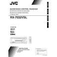
3.13 Removing the power supply board (See Fig.14) � Prior to performing the following procedures, remove the top cover. (1) From the top side of the main body, disconnect the parallel wires from the connector CN55 on the power transformer board 1. (2) Disconnect the card wire from the connector CN402 on the power supply board. (3) Disconnect the relay board from the connector CN71 on the power supply board. (4) Remove the three screws U attaching the power supply board. (5) Remove the power supply board from the hook e of the chassis base bracket in the direction of the arrow, take out the power supply board. (6) Turn over the power supply board, remove the solders from the soldered sections f attaching the wires.
CN402
Power supply board Headphone Card wire jack board
U
CN71
U
Soldered sections f
Tie bands
U
CN55
CN881 Main board Relay board
Power transformer board 1 Hook e of the chassis base bracket
Fig.14
3.14 Removing the headphone jack board (See Figs.14 and 15) � Prior to performing the following procedures, remove the top cover and front panel assembly. (1) From the top side of the main body, remove the tie bands attaching the parallel wire. (See Fig.14.) (2) Disconnect the parallel wire from the connector CN881 on the main board. (See Fig.14.) (3) From the front side of the main body, remove the nut and screw V attaching the headphone bracket to the front bracket. (See Fig.15.) (4) Remove the three screws U attaching the power supply board. (See Fig.14.) (5) Take out the headphone jack board from the inside of the chassis base while lifting the power supply board.
V
Headphone jack board Nut
Headphone bracket Front bracket
Fig.15
3.15 Removing the switch board (See Fig.16) � Prior to performing the following procedures, remove the top cover and front panel assembly. (1) From the back side of the front panel assembly, remove the two screws W attaching the switch board. (2) Take out the switch board, disconnect the wire from the connector CN432 on the switch board. 3.16 Removing the power switch board (See Fig.16) � Prior to performing the following procedures, remove the top cover and front panel assembly. (1) From the back side of the front panel assembly, remove the two screws X attaching the power switch board. (2) Take out the power switch board, disconnect the wire from the connector CN430 on the power switch board.
W
CN432
Front panel assembly CN430
X
Switch board
W
Power switch board
Fig.16
(No.MB003)1-11
|
|
|
> |
|