Nie masz w koszyku żadnych produktów
 
English Polski Spanish 
Szukaj instrukcji do
 

(e.g. AA-V20EG JVC, ZX-7 Sony )
PayPal 1000+ rating Secure, Encrypted Checkout.
 
Kto jest w sklepie?
Sklep przegląda 6043 gości 
Kategorie
Informacje
Polecamy
Strona główna >> JVC >> KDSH909R Instrukcja Serwisowa
 
 0 szt. w koszyku 

JVC KDSH909R
Instrukcja Serwisowa


Tweetnij o tym produkcie a dostaniesz $1.00 rabatu!
  • Zawiera schematy
  • Plik do pobrania
  • Format PDF
  • Kompletna instrukcja
  • Język: English
Cena: $4.99

Opis JVC KDSH909R Instrukcja Serwisowa

Kompletna instrukcja serwisowa w formie pliku PDF. Instrukcje serwisowe zazwyczaj zawierają schematy, diagramy drukowanych obwodów (PCB), schematy połączeń, schematy blokowe oraz katalog części. Instrukcje serwisowe są wykorzystywane glównie przez osoby naprawiające uszkodzony sprzęt.

Jeśli chcesz się dowiedzieć jak się obsługuje Twój telewizor, magnetowid, odtwarzacz mp3 itp. powinieneś raczej szukać instrukcji obsługi

Instrukcja jest dostępna w następujących językach:

Plik nie jest jeszcze gotowy
Musisz najpierw dokonać zakupu.

Recenzje produktu
Dla tego produktu nie napisano jeszcze recenzji!
Recenzje innych produktów
 ST-8077K TECHNICS Instrukcja Serwisowa by Adam Grążka;
...instruction is ok. ...instrukcja jest ok. Thanks/Dzięki
 T5 SANSUI Instrukcja Serwisowa by Adam Grążka;
Documentation made ​​available quickly and It is good quality. Thanks.

Tekstowy podgląd strony 16 (kliknij aby zobaczyć)
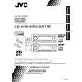
KD-SH909R Removing the trigger arm (See Fig.18 and 19)
Prior to performing the following procedure, remove the top cover, the connector board and the clamper unit. 1. Turn the trigger arm in the direction of the arrow to release the joint k and pull out upward.
Joint k

Trigger arm

CAUTION: When reassembling, insert the part l and m of the trigger arm into the part n and o at the slot of the chassis rivet assembly respectively and join the joint k at a time.

Chassis rivet assembly

Fig.18

Part n Trigger arm Part l Part m Part o

Chassis rivet assembly

Fig.19

Removing the top plate assembly (See Fig.20)
Prior to performing the following procedure, remove the top cover, the connector board, the chassis unit, and the clamper assembly. 1. Remove the screw H. 2. Move the top plate assembly in the direction of the arrow to release the two joints p.

Top plate assembly

H

Joints p

q

3. Unsolder the wire marked q if necessary.

Fig.20

1-16

Klienci kupując ten produkt kupili także

$4.99

KD-SH909R JVC
Instrukcja Obsługi

Kompletna instrukcja obsługi w formie pliku PDF. Plik PDF zostanie dostarczony na Twój adres email…
>
Parse Time: 0.297 - Number of Queries: 109 - Query Time: 0.08