|
|
|
Kto jest w sklepie?
Sklep przegląda 5964 gości |
|
Kategorie
|
|
Informacje
|
|
Polecamy
|
|
|
 |
|
|
Dla tego produktu nie napisano jeszcze recenzji!
 ;
Schematy są ale można wysilić się i zrobić kolorowy skan i o większej rozdzielczości. Wtedy schematy płytek będą czytelniejsze. Całość super jako wartość merytoryczna. Wszystkie dane potrzebne do podłączenia różnego rodzajów urządzeń takich gramofon, CD itd.
 ;
Szybko, sprawnie i tanio. Serwis godny polecenia. Będę polecał innym
;
Ogólnie jest OK, z wyjątkiem obrazu płyty głównej, który jest miejscami mało czytelny, ale można sobie poradzić.
;
Dokładna dokumentacja, pomogła w szybkiej naprawie telewizora. Dziękuję!
;
jedyne do czego mogę mieć zastrzeżenie to jakość zdjęć zawartych w przesłanej instrukcji serwisowej ponieważ są fatalnej jakości, praktycznie nieczytelne. tak poza tym jestem zadowolony to jest to czego szukałem.
3.1.7 EVR adjustment Some of the adjustments require the adjustment performed by the EVR system. The main unit have EEPROMs for storing the EVR adjustment data and user setups. Notes: � In the EVR adjustment mode, the value is varied with the channel buttons (+, �). The adjusted data is stored when the setting mode changes (from PB to STOP, when the tape speed is changed, etc.). Take care to identify the current mode of each adjustment item when making an adjustment. � When changing the address setting in the EVR adjustment mode, use the Jig RCU or the remote controller having numeric keypad with which a numeric code can be directly input. The remote control code of the Jig RCU corresponds to each of the digit keys on the remote controller as follows.
Digit-key 0 1 Code 20 21 23 22 23 4 24 5 25 6 26 789 27 28 29
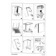
3.2 Mechanism compatibility adjustment Notes: � Although compatibility adjustment is very important, it is not necessary to perform this as part of the normal servicing work. It will be required when you have replaced the A/C head, drum assembly or any part of the tape transport system. � To prevent damaging the alignment tape in the compatibility adjustment, prepare a cassette tape (for self-recording/playback), perform a test on it by transporting it and making sure that the tape is not bent by the tape transport mechanisms such as in the guide rollers.(See Fig.3-2-2a) 3.2.1 Tension pole position Notes: � This adjustment must be performed every time the tension band is replaced.
Signal Mode Adjustment part Specified value (A) (B1) (B2) (F) (G)
� Back tension cassette gauge
[PUJ48076-2] � Play back position
� Eject end � Adjust pin [Mechansim assembly] � 25 - 51 gf�cm (2.45 � 5 � 10-3 Nm]
� As the counter indication and remaining tape indication are not displayed FDP during the EVR adjustment mode, check them on the TV monitor screen. � When performing the EVR adjustment, confirm that the FDP indication is changed to the EVR mode, as shown below.
FDP
(1) Play back the back tension cassette gauge (A). (2) Check that the indicated value on the left side gauge is within the specified value (G). (3) If the indicated value is not within the specified value (G), perform the adjustment in a following procedure.(See Fig.3-2-1a.) 1) Remove the top frame, cassette holder and side frames (L/R) all together. (See �section 2 mecha-nism�.) 2) Rotate the loading motor gear to move the control plate so that the triangular stamping to the left of the �P� stamping is aligned with the stamping (a) on the main deck. This positioning is mode (B1). 3) Adjust by turning the adjustment pin so that the tip of the tension arm is aligned with the stamping (b) on the main deck. 4) Rotate the reel disk (S) by about one turn clockwise and make sure that the round hole of the adjustment pin is located in the �OK� range. If it is outside this range, restart the adjustment from the beginning. After completion of the adjustment, rotate the loading gear motor to return it to the mode (B2) position.
TENSION ARM
Fig. 3-1-7a
EVR mode
CONTROL PLATE Stamping(a) Stamping(b) OK
NG ADJUST PIN
Fig. 3-2-1a
3-2
|
|
|
> |
|