|
|
|
Kto jest w sklepie?
Sklep przegląda 5914 gości |
|
Kategorie
|
|
Informacje
|
|
Polecamy
|
|
|
 |
|
|
Dla tego produktu nie napisano jeszcze recenzji!
 ;
Schematy są ale można wysilić się i zrobić kolorowy skan i o większej rozdzielczości. Wtedy schematy płytek będą czytelniejsze. Całość super jako wartość merytoryczna. Wszystkie dane potrzebne do podłączenia różnego rodzajów urządzeń takich gramofon, CD itd.
 ;
Szybko, sprawnie i tanio. Serwis godny polecenia. Będę polecał innym
;
Ogólnie jest OK, z wyjątkiem obrazu płyty głównej, który jest miejscami mało czytelny, ale można sobie poradzić.
;
Dokładna dokumentacja, pomogła w szybkiej naprawie telewizora. Dziękuję!
;
jedyne do czego mogę mieć zastrzeżenie to jakość zdjęć zawartych w przesłanej instrukcji serwisowej ponieważ są fatalnej jakości, praktycznie nieczytelne. tak poza tym jestem zadowolony to jest to czego szukałem.
A
B
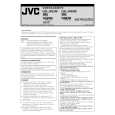
(4) Adjust the AUDIO OUT waveform and Control pulse waveform by turning the screws (1), (2) and (3) little by little until both waveforms reach maximum. The screw (1) and (3) are for adjustment of tilt and the screw (2) for azimuth.
Head base
Level drop at the guide roller (supply side) C D (2)
(1)
A/C head (3) Level drop at the guide roller (take-up side)
AUDIO OUT � Proper waveform variation: Always flat
CTL. P � Improper waveform variation: Higher
Lower
Fig. 2-3-2a 2.3.3 A/C head phase (X-value) Fig. 2-3-1c
Signal Mode
Improper Proper
(A1) (B) (C) (D) (E) (F) (G) (H)
Equipment Measuring point External trigger
� Alignment tape(SP, stairstep, NTSC) [MHP] � PB � Oscilloscope � TP106 (PB. FM) � TP111 (D.FF) � A/C head base [Mechanism assembly] � Maximum V.PB FM waveform � A/C head positioning tool [PTU94010]
(a) Guide roller
Adjustment part Specified value Adjustment tool
(b) Guide pole
Fig. 2-3-1d 2.3.2 Height and tilt of the A/C head Note: � Set a temporary level of the height of the A/C head in advance to make the adjustment easier after the A/C head has been replaced. (See Fig.2-2-6c.)
Signal Mode Equipment Measuring point External trigger Adjustment part Specified value (A) (B) (C) (D1) (D2) (E) (F) (G)
� Alignment tape(SP, stairstep, NTSC) [MHP] � PB � Oscilloscope � AUDIO OUT terminal � TP4001 (CTL. P) � TP111 (D.FF) � A/C head [Mechanism assembly] � Maximum waveform
(1) Play back the alignment tape (A1). (2) Apply the external trigger signal to D.FF (E), to observe the V.PB FM waveform at the measuring point (D). (3) Set the VCR to the manual tracking mode. (4) Loosen the screws (4) and (5), then set the A/C head positioning tool to the innermost projected part of the A/ C head. (See Fig. 2-3-3a.) (5) Turn the A/C head positioning tool fully toward the capstan. Then turn it back gradually toward the drum and stop on the second peak point position of the V.PB FM waveform output level. Then tighten the screws (4) and (5). (6) Perform the tracking operation and make sure that the V.PB FM waveform is at its maximum. If it is not at maximum, loosen the screws (4) and (5), and turn the A/C head positioning tool to bring the A/C head to a position, around where the waveform reaches its maximum for the first time. Then tighten the screws (4) and (5).
(1) Play back the alignment tape (A). (2) Apply the external trigger signal to D.FF (E), to observe the AUDIO OUT waveform and Control pulse waveform at the measuring points (D1) and (D2) in the ALT mode. (3) Set the VCR to the manual tracking mode.
2-17
|
|
|
> |
|