|
|
|
Kto jest w sklepie?
Sklep przegląda 5947 gości |
|
Kategorie
|
|
Informacje
|
|
Polecamy
|
|
|
 |
|
|
Dla tego produktu nie napisano jeszcze recenzji!
 ;
Schematy są ale można wysilić się i zrobić kolorowy skan i o większej rozdzielczości. Wtedy schematy płytek będą czytelniejsze. Całość super jako wartość merytoryczna. Wszystkie dane potrzebne do podłączenia różnego rodzajów urządzeń takich gramofon, CD itd.
 ;
Szybko, sprawnie i tanio. Serwis godny polecenia. Będę polecał innym
;
Ogólnie jest OK, z wyjątkiem obrazu płyty głównej, który jest miejscami mało czytelny, ale można sobie poradzić.
;
Dokładna dokumentacja, pomogła w szybkiej naprawie telewizora. Dziękuję!
;
jedyne do czego mogę mieć zastrzeżenie to jakość zdjęć zawartych w przesłanej instrukcji serwisowej ponieważ są fatalnej jakości, praktycznie nieczytelne. tak poza tym jestem zadowolony to jest to czego szukałem.
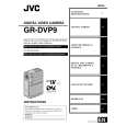
1.6 DISASSEMBLY/ASSEMBLY OF @ OP BLOCK ASSY (CCD BOARD ASSY) 1.6.1 Precautions 1. Carefully handle the CCD IMAGE SENSOR, OP LPF, LENS, etc. during the disassembly work. Pay the most careful attention to the surface of those parts not to get it soiled, scratched or dusty. If some of those surfaces gets soiled with fingerprints, etc., wipe it out with silicone paper, clean chamois, cleaning cloth or the like. 2. The new CCD IMAGE SENSOR is occasionally shipped from the factory as a protection seal is applied onto its transparent glass. If so, leave the protection seal as it is and remove it just before installing the CCD IMAGE SENSOR in the OP BLOCK ASSY. 3. The orientation of the OP LPF is an important factor for installation. If there some marking on the OP LPF, be sure to note it down before removing and to reassemble it very carefully as it was referring to the marking. 1.6.2 Disassembly method 1. Unsolder at the 14 points (SD@) and remove the CCD BOARD ASSY. 2. Remove the two screws (1, 2) and then remove the CCD BASE ASSY. NOTE@a: Carefully remove the CCD BASE ASSY, because the SPACE RUBBER and OP LPF may be removed together with the CCD IMAGE SENSOR.
NOTE@b:When replacing the CCD IMAGE SENSOR, don�t replace it individually but replace the CCD BASE ASSY in whole with a new one. 1.6.3 Assembly method 1. Install the OP LPF with the @ OP BLOCK ASSY. 2. With the SPACER RUBBER left attached to the CCD BASE ASSY, install the assembly in the OP BLOCK ASSY and clamp it using the two screws (1, 2). 3. Set the CCD BOARD ASSY in the CCD BASE ASSY, and fasten it by soldering at the 14 points (SD@). 1.6.4 Replacement of service parts Service parts to be supplied for the OP BLOCK ASSY are as follows. When replacing a part, be very careful not to get the FPC wire broken or damaged by soldering (overheating). 1. FOCUS MOTOR 2. ZOOM MOTOR 3. IRIS MOTOR UNIT NOTE@c: When soldering the FPC wire of the FOCUS MOTOR or ZOOM MOTOR during the replacement work, be sure to keep the tip of a soldering iron approximately 1 mm above the terminal.
IRIS MOTOR UNIT includes one FPC ASSY NOTE@d:The and two sensors.
�3
�5 �4
(S 12 b)
CCD SIDE OP SIDE BLUE
(S 12 b) (S 12 c)
CCD BOARD ASSY <05> (SD 12 ) (S 12 a)
�8
NOTE 12 d IRIS MOTOR UNIT (S 12 c)
�9
(S 12 c)
�1
�2
(S 12 a) CCD BASE ASSY NOTE 12 a,b SPACER RUBBER OP LPF NOTE 12 a
FOCUS MOTOR NOTE 12 c
�7 �6
(S 12 c) (S 12 c)
OP BLOCK
ZOOM MOTOR NOTE 12 c
� : 0.118 N�m (1.2 kgf�cm)
Fig. 1-6-1 1-10
|
|
|
> |
|