|
|
|
Kto jest w sklepie?
Sklep przegląda 5823 gości |
|
Kategorie
|
|
Informacje
|
|
Polecamy
|
|
|
 |
|
|
Dla tego produktu nie napisano jeszcze recenzji!
 ;
Bardzo dobra instrukcja. Zawiera wszystko co potrzeba, polecam!
 ;
Instrukcja jest OK. Schematy czytelne, opisane niektóre procedury.
;
Instrukcja bardzo czytelna. zawiera co potrzeba. Polecam
;
...instrukcja serwisowa w pełni czytelna i kompletna. Dziękuję!
;
Instrukcja Serwisowa jest kompletna i czytelna. Dziękuję!
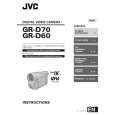
2.9 EMERGENCY DISPLAY Whenever some abnormal signal is input to the syscon CPU, an error number (E01, as an example) is displayed on the LCD monitor or (in the electronic view finder). In every error status, such the message as shown below alter nately appear over and over. � In an emergency mode, all operations except turning on/off the POWER switch are ineffectual. LCD display E01 Emergency mode LOADING Details
Example (in case of the error number E01):
E01 E01 REMOVE AND REATTACH BATTERY
UNIT IN
SAFEGUARD MODE
Possible cause
In the case the encoder posi- 1. The mechanism is locked during mode shift. tion is not shifted to the next 2. The mechanism is locked at the mechanism loading end, point though the loading motor because the encoder position is skipped during mechanism has rotated in the loading direcmode shift. tion for 4 seconds or more. This 3. No power is supplied to the loading MDA. error is defined as [E01]. In the case the encoder posi- 1. The mechanism is locked during mode shift. tion is not shifted to the next 2. The mechanism is locked at the mechanism loading end, point though the loading motor because the encoder position is skipped during mechanism has rotated in the unloading dimode shift. rection for 4 seconds or more. This error is defined as [E02]. In the case no REEL FG is produced for 4 seconds or more in the capstan rotation mode after loading was complete, the mechanism mode is shifted to STOP with the pinch roller set off. This error is defined as [E03]. However, no REEL EMG is detected in the SLW/STILL mode. 1. The idler gear does not engage with the reel disk well. 2. Though the idler gear and reel disk are engaged with each other, the tape is not wound because of overload to the mechanism. 3. No FG pulse is output from the reel sensor. 4. No power is supplied to the reel sensor. 5. Tape transport operation takes place with a cassette having no tape inside. 6. The tape slackens and no pulse is produced until the slack is taken up and the tape comes into the normal status.
E02
UNLOADING
E03
TU & SUP REEL FG
E04
DRUM FG
In the case there is no DRUM 1. The drum cannot be started or drum rotation is stopped beFG input in the drum rotation cause tape transport load is too high. mode for 4 seconds or more. 1) Tape tension is extremely high. This error is defined as [E04], 2) The tape is damaged or soiled with grease, etc. and the mechanism mode is 2. The DRUM FG signal is not received by the syscon CPU. shifted to STOP with the pinch 1) Disconnection in the middle of the signal line. roller set off. 2) Failure of the DRUM FG pulse generator (hall element). 3. No drum control voltage is supplied to the MDA. 4. No power is supplied to the DRUM MDA. In the case no CAPSTAN FG is 1. The CAPSTAN FG signal is not received by the syscon produced in the capstan rotaCPU. tion mode for 2 seconds or 1) Disconnection in the middle of the signal line. more. This error is defined as 2) Failure of the CAPSTAN FG pulse generator (MR ele[E06], and the mechanism ment). mode is shifted to STOP with 2. No capstan control voltage is supplied to the MDA. the pinch roller set off. 4. The capstan cannot be started or capstan rotation is However, no CAPSTAN EMG stopped because tape transport load is too high. is detected in the STILL/FF/ 1) Tape tension is extremely high. (Mechanical locking) REW mode. 2) The tape is damaged or soiled with grease, etc. (Tape tangling occurs, etc.) Fig.2-9-1
E05 E06
CAPSTAN FG
1-18 (No.86733)
|
|
|
> |
|