|
|
|
Kto jest w sklepie?
Sklep przegląda 5951 gości |
|
Kategorie
|
|
Informacje
|
|
Polecamy
|
|
|
 |
|
|
Dla tego produktu nie napisano jeszcze recenzji!
 ;
Schematy są ale można wysilić się i zrobić kolorowy skan i o większej rozdzielczości. Wtedy schematy płytek będą czytelniejsze. Całość super jako wartość merytoryczna. Wszystkie dane potrzebne do podłączenia różnego rodzajów urządzeń takich gramofon, CD itd.
 ;
Szybko, sprawnie i tanio. Serwis godny polecenia. Będę polecał innym
;
Ogólnie jest OK, z wyjątkiem obrazu płyty głównej, który jest miejscami mało czytelny, ale można sobie poradzić.
;
Dokładna dokumentacja, pomogła w szybkiej naprawie telewizora. Dziękuję!
;
jedyne do czego mogę mieć zastrzeżenie to jakość zdjęć zawartych w przesłanej instrukcji serwisowej ponieważ są fatalnej jakości, praktycznie nieczytelne. tak poza tym jestem zadowolony to jest to czego szukałem.
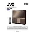
AV-61S902
4. REAR SIDE
REAR COVER
1) Remove 17 screws [A] and 6 screws [B]. 2) Take out the power cord panel and pull out the power cord through the hole. Take out the REAR COVER.
LINE FILTER SECTION
� Extract the MAIN CHASSIS. 1) Remove 2 screws [K], 3 screws [M] and 1 screw [N]. ! The LINE FILTER PWB ASS�Y shield cover, power section smaller EXHAUST COOLING FAN and larger EXHAUST COOLING FAN are attached to the line filter board base.
REAR SIDE PANEL
� Take out the REAR COVER. 1) Remove 6 screws [C]. ! Both left and right have the same construction.
MAIN DRIVE PWB ASS�Y
� Extract the MAIN CHASSIS. 1) Disengage connector (017). 2) Support the MAIN DRIVE PWB ASS�Y and remove 4 screws [O]. 3) Disengage connectors (AA/AC/AN/C/W) and take out the MAIN DRIVE PWB ASS�Y. ! The shield cover is attached by tabs at both sides of the MAIN DRIVE PWB ASS�Y.
REAR TERMINAL BOARD
� Take out the REAR COVER. 1) Remove 7 screws [D] and 3 screws [E] (with washers). 2) Pull outward and take out the REAR TERMINAL BOARD.
DIGITAL INPUT PWB ASS�Y
� Take out the REAR TERMINAL BOARD. 1) Remove 2 screws [F] and take out the DIGITAL INPUT PWB ASS�Y.
MAIN CHASSIS EXTRACTION and STANDING
� Take out the REAR COVER. � Take out the REAR TERMINAL BOARD. " Where required, take out the REMOTE CONTROL SENSOR PWB ASS�Y and FRONT JACK PWB ASS�Y. " Prepare a 30cm high by 60cm wide seating for standing the MAIN CHASSIS. 1) Where necessary, disengage the clamps at the MAIN CHASSIS perimeter. 2) Grasp both sides of the rear and pull the MAIN CHASSIS outward. 3) Disengage the MAIN CHASSIS front clamps. 4) Disengage 5 tabs [G] at the MAIN CHASSIS bottom and take out the front board base (SYNC. SEPARATION PWB ASS�Y). 5) Position the front downward, extract and set the MAIN CHASSIS on its side on the seating with the rear terminal section at the left side in the bottom base. ! As required for operation checks, attach the FRONT CONTROL PWB ASS�Y, REMOTE CONTROL SENSOR PWB ASS�Y and other components. ! The MAIN CHASSIS is quite heavy. Care is needed in handling, particularly to prevent toppling over when stood on its side.
POWER SECTION COOLING FAN (EXHAUST)
� Extract the MAIN CHASSIS. 1) Remove 2 screws [H]. 2) Remove 2 screws [I] (with washers). 3) Disengage connector (AQ) and take out the smaller EXHAUST COOLING FAN. 4) Remove 2 screws [J] and 2 screws [K]. 5) Remove 2 screws [L]. 6) Disengage connector (P) and take out the larger EXHAUST COOLING FAN.
10
No. 51775
|
|
|
> |
|