|
|
|
Kto jest w sklepie?
Sklep przegląda 6043 gości |
|
Kategorie
|
|
Informacje
|
|
Polecamy
|
|
|
 |
|
|
Dla tego produktu nie napisano jeszcze recenzji!
 ;
Bardzo dobra jakość skanu, przystępna cena. Instrukcja serwisowa okazała się przydatna przy "reanimowaniu" dwudziestoparoletniego decka, który teraz pięknie gra :)
;
...instruction is ok.
...instrukcja jest ok.
Thanks/Dzięki
;
Documentation made available quickly and It is good quality. Thanks.
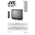
AV-36360 AV-36S36 AV-36330 AV-36S33 AV-36320
SPECIFIC SERVICE INSTRUCTIONS
DISASSEMBLY PROCEDURE
REMOVING THE REAR COVER
" Unplug the power plug. 1. As s hown in Fig.2, remove the
REMOVING THE SPEAKER
" After removing the rear cover and chassis base. 1. As s hown in Fig.2, r emove the
11 screws marked ! .
2 screws marked * .
2. Remove the rear c over toward you. Note : When reinstalling the rear cover, c arefully pus h it inward after inserting the chassis into the rear c over groove.
2. Follow the s ame steps when removing the other hand speaker.
CHECKING THE MAIN PW BOARD
1. To check the backs ide of the MAIN PW Board. (1) Pull out the c hassis base. (Refer to REMOVING THE CHASSIS BASE). (2) Erect the chassis vertic ally so that you can easily chec k from the backside of the MAIN PWB.
REMOVING THE CHASSIS BASE
" After removing the rear cover. remove the 1. Slightly raise the both s ides of the chassis base by hand, and
2 claws
marked " (Fig.1 and Fig.2) under the both
sides of the chassis from the chassis rail. 2. As shown in Fig.1, draw the chassis base backward along the chassis rail marked # in the arrow direction marked $(Fig.2.). (If necess ary, detac h the wire clamp, connec tor�s etc.) Note : When conducting a c hec k with power supplied, be sure to confirm that the CRT earth wire is c onnected to the CRT SOCKET PWB and the MAIN PWB.
CAUTION
" When erecting the chass is, be c areful so that there will be no contacting with other PWB. " Before turning on power, make sure that the CRT earth wire and other connectors are properly connected.
WIRE CLAMPING AND CABLE TYING
1. Be sure to clamp the wire. 2. Never remove the c able tie used for tying the wires together. Should it be inadvertently removed, be sure to tie the wires with a new c able tie.
REMOVING THE TERMINAL BOARD
" After removing the rear cover. 1. As s hown in Fig.2, remove the
4 screws marked%& . %& 3
screws FRONT CABINET MAIN PWB
(In case of dis assembly the AV-36320, remov e the
marked &.) 2. When you pull out the TERMINAL BOARD, it can be removed.
REMOVING THE FRONT CONTROL PW BOARD
" After removing the rear cover and chassis base . 1. As s hown in Fig.2, remove the
2 screws
marked ' attached the
C
FRONT CONTROL PWB with the front cabinet. 2. Then remove the FRONT CONTROL PWB.
REMOVING THE FRONT AV IN PW BOARD
" After removing the rear cover and chassis base.
CHASSIS BASE
( at the front input terminal. 2. As s hown in Fig.2, pull the claw marked ) .
3. Then remove the FRONT AV IN PWB. Fig. 1
1. Remove the screw marked
B
8
No. 51950
|
|
|
> |
|