|
|
|
Kto jest w sklepie?
Sklep przegląda 5664 gości i
4 zarejestrowanych klientów |
|
Kategorie
|
|
Informacje
|
|
Polecamy
|
|
|
 |
|
|
Dla tego produktu nie napisano jeszcze recenzji!
 ;
Bardzo dobra jakość skanu, przystępna cena. Instrukcja serwisowa okazała się przydatna przy "reanimowaniu" dwudziestoparoletniego decka, który teraz pięknie gra :)
;
...instruction is ok.
...instrukcja jest ok.
Thanks/Dzięki
;
Documentation made available quickly and It is good quality. Thanks.
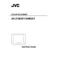
AV-29M201
ADJUSTMENT OF MTS CIRCUIT
Item MTS INPUT LEVEL check Measuring instrument Test point Adjustment part No.2 IN LEVEL Description 1. Select the �No.2 IN LEVEL� of the SOUND mode in SERVICE MENU. 2. Verify that the �No.2 IN LEVEL� is set at its initial setting value. MTS STEREO VCO adjustment Signal generator Frequency counter R OUT No.3 FH MON [AUDIO OUT] No.4 ST VCO 1. Receive a NTSC RF signal (non modulated sound signal) from the antenna terminal. 2. Select the �No.3 FH MON� of SOUND mode in SERVICE MENU, change the setting value from 0 to 1. 3. Connect the frequency connector to R OUT RCA pin of the AUDIO OUT. 4. Select the �No.4 ST VCO�. 5. Confirm the initial setting value of the �No.4 ST VCO�. 6. Adjust the �No.4 ST VCO� so that the frequency counter will display 15.73kHz± 0.1kHz. 7. Select the �No.3 FH MON� of the SOUND mode, and reset the setting value from 1 to 0. MTS SAP VCO adjustment Signal generator Frequency counter MPX No.9 5FH MON. 1. Receive a NTSC RF signal (non modulated sound signal) from the antenna terminal. 2. Connect between pin 4 of MPX connector and GND
Connector 4 pin SDA No.10 SAP VCO. 3 pin GND [MAIN PWB] R OUT [AUDIO OUT]
(pin 3 of MPX connector) through 1MΩ resistor. 3. Select the �No.9 5FH MON.� of the SOUND mode in SERVICE 4. 5. 6. 7. MENU, and reset the setting value from 0 to 1. Connect the frequency connector to R OUT RCA pin of the AUDIO OUT. Select the �No.10 SAP VCO�. Confirm the initial setting value of �No.10 SAP VCO�. Adjust the �No.10 SAP VCO� so that the frequency connector will display 78.67kHz±0.5kHz. 8. Select the �No.9 5FH MON.� of the SOUND mode, and reset the setting value from 1 to 0.
MTS FILTER check
No.6 FILTER
1. Select the �No.6 FLTER� of the SOUND mode in SERVICE MENU. 2. Verify that the �No.6 FLTER� is set at its initial setting value.
MTS SEPARATION adjustment
TV audio multiplex signal generator Oscilloscope
L OUT No.7 LOW SEP. R OUT [AUDIO OUT] No.8 HI SEP.
1. Input a stereo L signal (300Hz) from the TV Audio multiplex signal generator to the antenna terminal. (NTSC) 2. Connect an oscilloscope to L OUT RCA pin of the AUDIO OUT, and display one cycle portion of the 300Hz signal. 3. Change the connection of the oscilloscope to R OUT RCA pin of the AUDIO OUT, and enlarge the voltage axis. 4. Select the �No.7 LOW SEP.� of the SOUND mode in SERVICE MENU. 5. Confirm the initial setting value of the �No.7 LOW SEP.�. 6. Adjust the �No.7 LOW SEP.� so that the stroke element of the 300Hz signal will become minimum. 7. Change the signal to 3kHz, and similarly adjust the �No.8 HI SEP.�.
L-Channel signal waveform
R-Channel crosstalk portion Minimum
1 cycle
No. 51731
23
|
|
|
> |
|