|
Dla tego produktu nie napisano jeszcze recenzji!
 ;
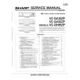
...instruction is ok.
...instrukcja jest ok.
Thanks/Dzięki
;
Documentation made available quickly and It is good quality. Thanks.
AV-20N3PX
REPLACEMENT OF CHIP COMPONENT
s CAUTIONS
1. 2. 3. 4. Avoid heating for more than 3 seconds. Do not rub the electrodes and the resist parts of the pattern. When removing a chip part, melt the solder adequately. Do not reuse a chip part after removing it.
s SOLDERING IRON
1. Use a high insulation soldering iron with a thin pointed end of it. 2. A 30W soldering iron is recommended for easily removing parts.
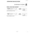
s REPLACEMENT STEPS 1. How to remove Chip parts
q Resistors, capacitors, etc. (1) As shown in the figure, while pushing the chip part with tweezers, alternately melt the solder at its each end.
2. How to install Chip parts
q Resistors, capacitors, etc. (1) Apply solder to the pattern as indicated in the figure.
(2) Grasp the chip part with tweezers and place it on the solder. Then heat and melt the solder at both ends of the chip part. (2) Shift the chip part with tweezers and remove it.
q Transistors, diodes, variable resistors, etc. (1) Apply extra solder to each lead.
q Transistors, diodes, variable resistors, etc. (1) Apply solder to the pattern as indicated in the figure. (2) Grasp the chip part with tweezers and place it on the solder. (3) First solder lead A as indicated in the figure.
SOLDER
SOLDER
A (2) As shown in the figure, while pushing the chip part with tweezers, alternately melt the solder at its each lead. Then, shift and remove the chip part. B C (4) Then solder leads B and C. A B C
Note : After removing the part, remove remaining solder from the pattern.
No. 56049
9
|