|
|
|
Kto jest w sklepie?
Sklep przegląda 5891 gości |
|
Kategorie
|
|
Informacje
|
|
Polecamy
|
|
|
 |
|
|
Dla tego produktu nie napisano jeszcze recenzji!
 ;
jedyne do czego mogę mieć zastrzeżenie to jakość zdjęć zawartych w przesłanej instrukcji serwisowej ponieważ są fatalnej jakości, praktycznie nieczytelne. tak poza tym jestem zadowolony to jest to czego szukałem.
 ;
Wszystko w porządku.
Instrukcja czytelna i kompletna.
Dziękuję.
all right!
thank you.
;
Bardzo dobra instrukcja. Zawiera wszystko co potrzeba, polecam!
;
Instrukcja jest OK. Schematy czytelne, opisane niektóre procedury.
;
Instrukcja bardzo czytelna. zawiera co potrzeba. Polecam
Safety Check after Servicing
Examine the area surrounding the repaired location for damage or deterioration. Observe that screws, parts and wires have been returned to original positions, Afterwards, perform the following tests and confirm the specified values in order to verify compliance with safety standards. 1. Insulation resistance test Confirm the specified insulation resistance or greater between power cord plug prongs and externally exposed parts of the set (RF terminals, antenna terminals, video and audio input and output terminals, microphone jacks, earphone jacks, etc.). See table 1 below. 2. Dielectric strength test Confirm specified dielectric strength or greater between power cord plug prongs and exposed accessible parts of the set (RF terminals, antenna terminals, video and audio input and output terminals, microphone jacks, earphone jacks, etc.). See table 1 below. 3. Clearance distance When replacing primary circuit components, confirm specified clearance distance (d), (d�) between soldered terminals, and between terminals and surrounding metallic parts. See table 1 below. Chassis Fig. 8 4. Leakage current test Confirm specified or lower leakage current between earth ground/power cord plug prongs and externally exposed accessible parts (RF terminals, antenna terminals, video and audio input and output terminals, microphone jacks, earphone jacks, etc.). Measuring Method : (Power ON) Insert load Z between earth ground/power cord plug prongs and externally exposed accessible parts. Use an AC voltmeter to measure across both terminals of load Z. See figure 9 and following table 2.
d
d'
Power cord, primary wire
a
b
Externally exposed accessible part
Z V
c
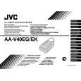
Fig. 9 5. Grounding (Class 1 model only) Confirm specified or lower grounding impedance between earth pin in AC inlet and externally exposed accessible parts (Video in, Video out, Audio in, Audio out or Fixing screw etc.). Measuring Method: Connect milli ohm meter between earth pin in AC inlet and exposed accessible parts. See figure 10 and grounding specifications.
AC inlet
Exposed accessible part
Grounding Specifications Region Grounding Impedance (Z) Z � 0.1 ohm Z � 0.5 ohm USA & Canada Europe & Australia
Earth pin Milli ohm meter
Fig. 10
AC Line Voltage 100 V 100 to 240 V 110 to 130 V 110 to 130 V 200 to 240 V
Region Japan USA & Canada Europe & Australia
Insulation Resistance (R) R � 1 M�/500 V DC 1 M� � R � 12 M�/500 V DC R � 10 M�/500 V DC
Dielectric Strength AC 1 kV 1 minute AC 1.5 kV 1 miute AC 1 kV 1 minute AC 3 kV 1 minute (Class 2) AC 1.5 kV 1 minute (Class 1)
Clearance Distance (d), (d') d, d' � 3 mm d, d' � 4 mm d, d' � 3.2 mm d � 4 mm d' � 8 mm (Power cord) d' � 6 mm (Primary wire)
Table 1 Specifications for each region
AC Line Voltage 100 V 110 to 130 V 110 to 130 V 220 to 240 V
Region Japan USA & Canada
0.15 µF
Load Z
Leakage Current (i) i � 1 mA rms i � 0.5 mA rms
1.5 k�
a, b, c Exposed accessible parts Exposed accessible parts Antenna earth terminals Other terminals
1 k�
Europe & Australia
2 k�
50 k�
i i i i
� 0.7 mA peak � 2 mA dc � 0.7 mA peak �
2 mA dc
Table 2 Leakage current specifications for each region Note: These tables are unofficial and for reference only. Be sure to confirm the precise values for your particular country and locality.
2
S40888-01
|
|
|
> |
|